

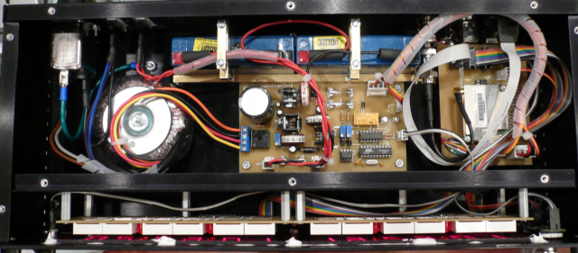
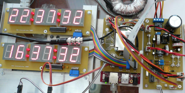
The genesis of this clock stems from one of my other hobbies, Ham Radio. I wanted a reasonably accurate clock that would display both local and UTC time on a large LED display. Everything I could find missed the mark by at least one feature. So I set out to design a clock with the above features, and also with the additional feature of being a stratum one NTP time Server, that is synchronized to a GPS’s pulse per second (PPS) signal.
At the heart of the system I am using a small single board computer based upon an ARM processor running Linux. I actually purchased the board in 2006 for another undertaking that is still in my long list of projects. The TS-7400 Computer-on-Module is built and sold by Technologic Systems. In the configuration I bought the SBC I paid $155 for a single unit. Mine has 64MB of RAM, 32MB of Flash, a battery backed up real time clock (RTC), and runs a 200Mhz ARM processor. I’ve configured the board to boot and mount a file system from a 2Gig SD card. I love this board! It runs a full version of Debian Linux. To date, every standard software package I’ve loaded complies and runs without any trouble.
I need to chime in about Technologic Systems here before I continue. These guys are awesome, great, fantastic, fill in the blank… As I mentioned above, I bought my board and development kit four years ago. While developing this project I ran into a snag with the bios. If I would have used the board for my original project back in 2006 I would have found out immediately. But instead I found out three years after the warranty period expired. None the less, I contacted tech support at Technologic Systems to work through the problem. Their tech support team is a first class operation staffed with knowledgeable people. After several emails back and forth it was determined that I needed to have my board re-flashed. I packaged up the board and shipped it back to them. Within a week or so I had my TS-7400 back fully functioning as originally spec’d! I even received a discount on the labor after speaking with Bob, their President/CEO, and explaining that I was building this for an open source project. (Thanks Bob, I paid you back a little this week by ordering two more boards.) Technologic Systems is also active in a Yahoo TS-7000 group supporting their products. I’ve found this group invaluable while developing this project.
The remainder of the hardware on this system consists of an OEM Garmin GPS, a high quality GPS antenna purchased through Ebay, an interface board, two display boards, a power supply with battery backup, and a power supply monitor that interacts with the TS-7400. The complete system, schematics and software are detailed below.
With the exception of the power supply monitor code, which is written in assembly, everything else is written in C. The Linux Kernel needed to be patched to allow NTPD to interact with the Kernel with microsecond precision. I wrote a device driver that is loaded as a module to sync from the GPS’s PPS signal. The two other programs are those that drive the clock display and poll the power supply monitor that will halt the system for a clean shutdown.

The TS-7400 is a complete fairly complete Linux Single Board Computer; you just need to add your own custom I/O. The board is based upon a Cirrus ARM 9 CPU running at 200Mhz. Onboard I/O includes a 10/100 Ethernet port, 2 USB ports, 3 TTL level serial ports, 20 general I/O lines, SPI, and 4 Analog to Digital convertors
As configured from Technologic Systems, the TS-7400 boots from flash and also has a small file system in flash, I opted to use a larger SD file system. I’ve actually developed everything right on the system itself. The only software I don’t compile on the TS-7400 is the Linux kernel, which I cross compile on one of my other machines and then “dd” it onto the SD card. With my original board I also purchased their development kit which includes the TS-9441 peripheral board, power supply, a 512MB SD card with a Debian distribution, and a few other useful items. If you are a first time TS-7400 devloper I’d suggest going the same route. The TS-9441 can save your bacon if you hose the TS-7400, as it allows you to restore the original factory setup. I’ve since set up my own SD drives on 2GIG cards. The 512MB cards are a bit on the small side once you start loading additional software. I bought several of the the SanDisk 2GB cards so if I trash one I just swap in another and keep going. You can also try differnet options for Kernels and have an easy way to compare and roll back if needed. Here are the following steps to set up the base 2G SD card and the base software.
Before writing my own PPS module I spent some time time looking at how others have implemented the PPS interface.
I wrote my own device driver that can be loaded as a Linux module. Access to the driver is based upon RFC 2783, a Pulse-Per-Second API for UNIX-like Operating Systems. I’ve only built the minimal implementation required by the RFC. So far in my testing it works well with NTPD. Basic operation of the driver is to record a time stamp each time the PPS signal is received from the GPS. NTPD periodically requests the time stamp through the PPS API and adjusts the system clock to more closely match the PPS sync.
/etc/ntp.conf
server bonehed.lcs.mit.edu server clock.isc.org server clock.via.net server 127.127.20.0 minpoll 4 maxpoll 4 prefer server 127.127.22.0 minpoll 4 maxpoll 4 fudge 127.127.22.0 flag2 0 stratum 0 driftfile /etc/ntp.drift |
My rc script (Does not show mod_pps loading, which needs to happen first.)
#!/bin/sh ln -s /dev/ttyTS0 /dev/gps0 PATH=/sbin:/bin test -f /usr/local/bin/ntpdate || exit 0 test -f /usr/local/bin/ntpd || exit 0 /usr/local/bin/ntpdate -b bonehed.lcs.mit.edu /usr/local/bin/ntpdate -b clock.isc.org /usr/local/bin/ntpdate -b clock.via.net /usr/local/bin/ntpd exit 0 |
Ntpq output
     remote           refid      st t when poll reach   delay   offset  jitter
==============================================================================
+bonehed.lcs.mit .PPS.            1 u 1044 1024  377  103.685   11.753   2.714
+clock.isc.org   .GPS.            1 u  382 1024  377   26.066   -7.363   5.145
*clock.via.net   .GPS.            1 u  478 1024  377   26.264   -1.785   0.674
xGPS_NMEA(0)     .GPS.            0 l    8   16  377    0.000  -593.95  19.067
xPPS(0)          .PPS.            0 l   10   16  377    0.000   -0.002   0.061
|
I am actually quite pleased with the clock software that is used to display the time. Being a programmer that likes to do things in a simple and elegant method I broke the clock up into different processes. Data passes between the processes using FIFO’s. There is a display writer process, a main clock loop, and two more processes that monitor the mechanical encoders. If motion is detected on the encoders the data is passed through one of the FIFO’s to the managing process for action.
I came up with an incredibly simple way to detect direction of the encoders. If you look at the functions that process input from the encoders you’ll see that I wait for a state change. Next I OR together the left shifted “last” state together with the new state. This four bit value is used to address an array of 16 states, of which only 8 values are valid. Every other implementation I have seen uses a complex switch or if statements.
To reduce the load of the tight input loop that monitor the encoder inputs I sleep between queries. Once a change is detected I loop at a much higher rate as to not miss an event. After a period of time I resume the slower rate of input. If you watch using a “top” you’ll see the effect on the system.
The mode switch selects between UTC/LOCAL, UTC/DATE, or LOCAL/DATE display modes.
The Power Supply Monitor daemon queries the microcontroller monitoring the power supply voltages. If the voltages fall out of spec the system can initiate a clean shutdown as well as tell the PS monitor to turn off power to the TS-7400.
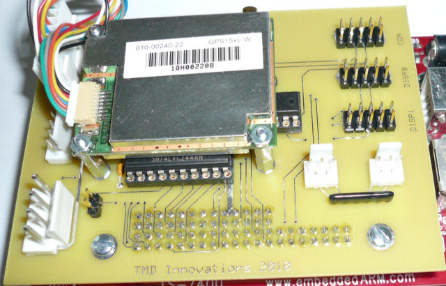
Interface board mounted to the TS-7400 with GPS mounted.
The interface board plugs directly onto the 40 and 26 pin header connectors of the TS-7400. Buffer chips convert the signals coming to and from the TS-7400 to be compatible with the 5 volt logic levels of the peripherals. An RS232 driver chip provides for the console port as well as the incoming GPS NMEA signal. Two mechanical encoders are connected to the interface board for the display brightness and mode controls.
Both the A and B 5 volt supplies are connected to the interface board. The A supply only powers the display boards, where the battery backed up B supply powers the TS-7400, GPS, and also the interface board itself. If line voltage fails the TS-7400 remains powered and sync’d to the GPS signal. The power supply monitor is also connect to the interface board, although the serial lines are kept at TTL levels as delivered from the microcontroller.
There are two different types of 244 buffers on the interface board. The 74LVC244 is a low voltage CMOS buffer. Its inputs are 5 volt tolerant and protect the TS-7400 inputs which are not 5 volt tolerant. The other buffer is a 74HCT244 which will accept the 3 volt output and convert them to 5 volt TTL levels for the display drivers. Do not swap them or your circuit will not work.
 |
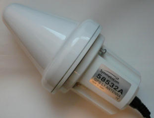 |
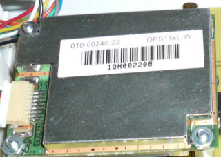
The GPS is a small OEM module from Garmin, the 15xH/15xL part number 010-00240-22. I also ordered the MCX to BNC adapter cable, part number 010-10121-00. The GPS cost 53.50 and the cable 25.00. The antenna, I bought several years ago through Ebay, is a Symmetricom P/N 58532A. I use an N to BNC adaptor on the antenna. Then I run a 50 ohm coax cable with BNC connectors between the antenna and MCX to BNC cable bought from Garmin. Any good external GPS antenna should be suitable. I like the Symmetricom because of the gain in the case where I need to run a longer cable between the GPS and antenna. The antenna is powered through the cable by voltage provided by the GPS module. The board will supply up to 60ma to the antenna.
The Garmin GPS module has an RS232 serial interface that connects to the interface board, as well as a TTL logic level pulse per second (PPS) line. You can substitute in any GPS that meets these requirements, though a different GPS won’t bolt nicely to the interface board. By default the GPS “talks” a lot of NMEA strings that you don’t need. To “quiet” the chatter down you can use minicom to talk to the GPS through /dev/ttyTS0 at 4800 baud and issue the commands to silence the unwanted messages. The only message I kept is the GPRMC string. For specifics you’ll want to refer to the NTPD NMEA reference clock driver documentation.
$GPRMC,030422,A,4035.5922,N,11148.3974,W,000.0,092.4,280710,013.2,E*6A
$GPRMC,030423,A,4035.5922,N,11148.3974,W,000.0,092.4,280710,013.2,E*6B
$GPRMC,030424,A,4035.5922,N,11148.3974,W,000.0,092.4,280710,013.2,E*6C
$GPRMC,030425,A,4035.5922,N,11148.3974,W,000.0,092.4,280710,013.2,E*6D
$GPRMC,030426,A,4035.5922,N,11148.3974,W,000.0,092.4,280710,013.2,E*6E
$GPRMC,030427,A,4035.5922,N,11148.3974,W,000.0,092.4,280710,013.2,E*6F
$GPRMC,030428,A,4035.5922,N,11148.3974,W,000.0,092.4,280710,013.2,E*60
$GPRMC,030429,A,4035.5921,N,11148.3974,W,000.0,092.4,280710,013.2,E*62
$GPRMC,030430,A,4035.5921,N,11148.3974,W,000.0,092.4,280710,013.2,E*6A

The two display boards use a Maxim Serially Interfaced Display Driver chip, the MAX7219, which multiplex six one inch seven segment displays. The driver boards connect to the TS-7400 using a three line serial interface, data, clock, and a load line. The boards share the clock and data lines, but have their own load line from the TS-7400. The colon LEDS are connected to the driver as the decimal points for digits 2, 3, 4, and 5. When a display is showing the date the LEDS will be off to differentiate that mode. In dual time zone mode the displays show local and UTC time. Two other modes can be selected that display local time and date, or UTC time and date.

A lot of effort went into the design of the power supplies, there were three primary concerns. First, the EXT2 SD file system on the TS-7400 is vulnerable to corruption should the power fail. Second, I wanted to design the clock to be highly available as a network device. And third, not having the power go up and down allows NTPD to stay “tuned” to the PPS signal. Incorporating battery backup into my design would solve all of these requirements.
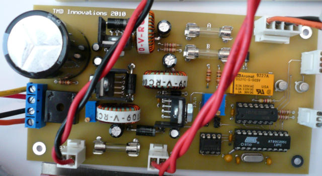
The power supply is built using three regulated voltage sources. First a transformer steps down the line voltage to 18 volts where it is rectified and filtered providing around 25 volts to the regulators. One regulator provides the 5 volt “A” voltage to the display boards. During a power failure I opted to save the power and not show the time on the displays, therefore the need to two 5 volt sources. Also connected to the 25 volt filtered source is the 13.5 volt regulator. This supply will maintain a “float” voltage on the 1.4 amp gel cells; it also provides the input voltage to the 5 volt “B” regulator. In the case where the line voltage fails the batteries take over where the 13.5 volt regulator left off. The 5 volt “B” regulator remains running as long as the batteries maintain voltage high enough. Although, this regulator can be shut down by a command to the power supply monitor.
The switching regulators are very efficient; little heat is generated by them. In open air they all run under 100 degrees ahrenheit. All three are National Semiconductor Simple Switcher regulators. Except for the adjustable regulator they take only 5 external parts to complete.
The Power Supply Monitor uses an Atmel AT89C2051 microcontroller wired to a TLC0832 dual channel serial ADC to monitor
the “A” 5 volt supply and the battery voltage. When the board is first set up voltages at the test points need to be adjusted
below the value of the 5 volt “B” rail to prevent lockup of the ADC’s. The power supply monitor on its own will not turn off
the “B” regulator. When the voltage drops to a determined voltage the daemon running on the SBC will initiate a system shutdown
to prevent an unclean un-mounting of the SD file system.
Complete
TO DO: Start up scripts.
ExpressPCB - printed circuit board manufacturing service - free schematic and board layout software.